Blue Peter Dinghy - Transom Plate
When our Blue Peter arrived, it didn't have a transom plate, presumably long since rotted away. I made one for it from a piece of oak that I varnished well if I recall correctly. This has worked fine, but since I've had to take this off, I discovered the ever so faint outline of the original is still visible on the hull, so I traced it and put it into a CAD diagram. I'm not sure how thick it was originally, but can guess at an inch or some other common imperial measurement given the age of the boat.
I've printed this at 1:1 size and it's a fair match for my tracing. It was created using the FreeCAD (v0.19) parametric modelling tool. It took a little getting used to this app, and I've certainly not mastered it, but I've done enough things in it to get the basic shape. Having never had the original to measure, I cannot be certain this is accurate, but its as close as I could to the overall shape excepting I have redrawn the cut-out a the top using a Bezier curve to follow the curve of the boat better than the old one might have. NOTE, I have discovered that the file will not open properly in older versions of FreeCAD. If it doesn't open for you, double check this first.
If you wanted to modify the shape yourself, it is shaped using an oval. The dimension of which is configurable in the sketch to the far left of the diagram. If you increase the oval length, the curve of the transom is reduced.
You may wish to drill all holes at 5mm diameter. The 4 lower holes on my boat have 4mm screws into a wooden plate inside the transom so don't need to be 5mm. This wooden plate is about 10mm thick at a push, so it might be worth swapping for 5mm bolts with a jack nut.... I'll have a think about this. It seems to work okay at the moment. I can't tell if the wood is rotten because it has been fibre-glassed over and isn't in an accessible location. I've actually filled the old holes now too as they were very queerly located. These bolts or screws are below the waterline though so perhaps a jacknut (and the larger hole it requires might cause more water ingress for minimal benefit.
Do you have an original transom plate on yours? Can you provide me with the thickness and material detail? If so, please get in touch. I've presumed 30mm+ from the photographs I've found on the web, but really it's the 2D shape I was keen to capture. It must have been a heavy lump if that thick!
NOTE: VERY IMPORTANT. I have been given a second rudder stock for a Blue Peter Dinghy. This has the rudder gudgeons (and one presumes pintles too) further apart than on my existing one. Check yours before blindly drilling the pintle holes in the transom plate as per my CAD file.
Download FreeCAD Transom Plate CAD File or as an A3 size PDF (can be printed A4 as a poster with Adobe Reader. If I come to make one, I'll print the PDF full-size, cut it out and use it as a template. All measurements have been placed internal to the part so I'll still have them all.
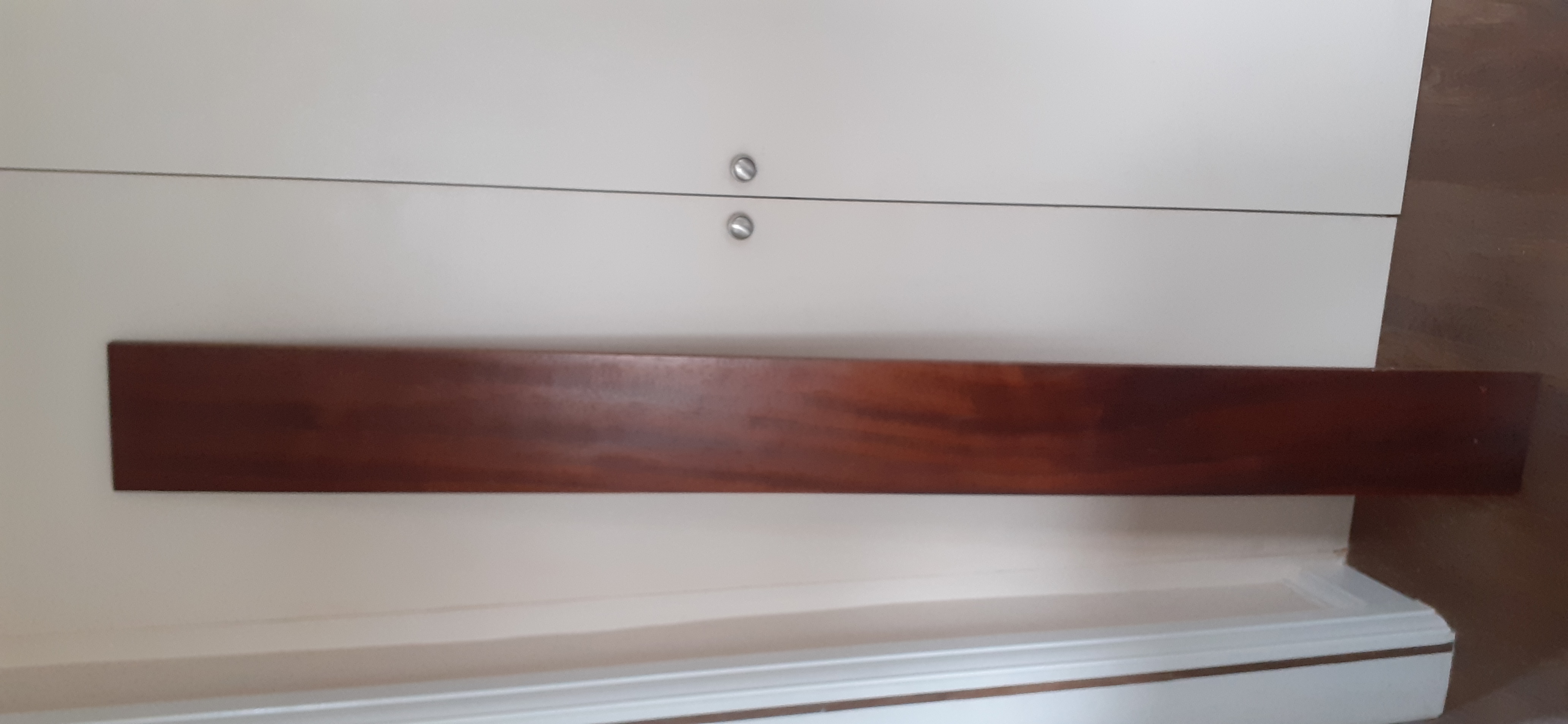
UPDATE: I've just been offered a lovely Mahogany (possible Sapele) board via Freecycle from Liz and Rod, so fingers crossed I'll be able to use the router and some epoxy to make this into a shorter wider board before routing out the shape I took from the shadow in the gelcoat.
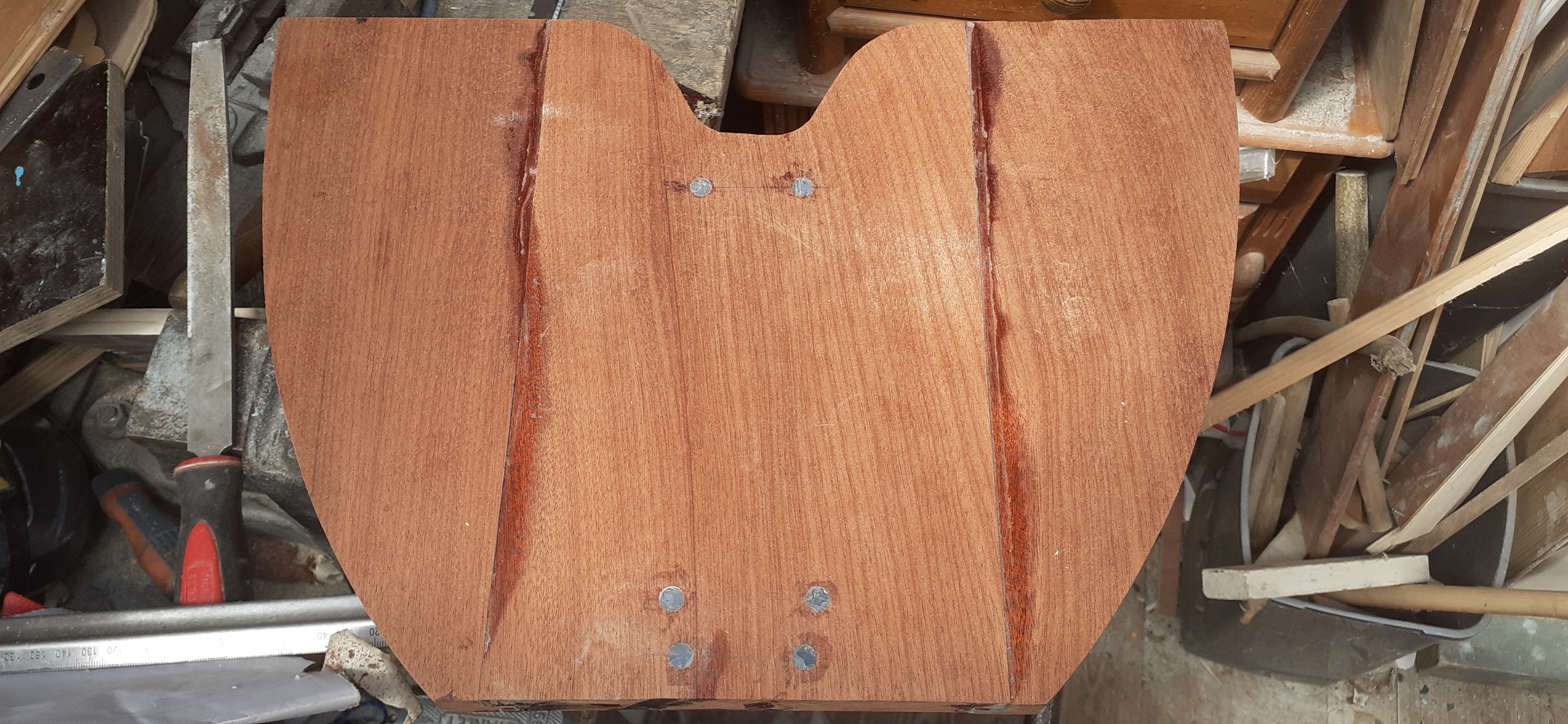
Today I got cracking on the transom plate. I thought the plank was true, but sadly it wasn't quite, so I used the plunge saw on a rail to get the longest sides both straight as a die and parallel to each other, then squared the ends. Next I cut the 3 short planks out to make the desired width (mistake! - I should have thought about it harder and done two longer lengths joined lengthways instead).
To strengthen the joint, I used a router to add a 10mm step on each board that I then coated well in polyester resin mixed with colloidal silica to a thick paste, then pressed together in a lap joint. The board is a little warped, so because I just pressed the boards to and allowed the epoxy to set naturally, there is a lip here and there at the joints, but either the planer or sander will cure this. Plenty of resin was squeezed out so I'm confident its a good joint.

When I was experimenting, I made a transom plate from a piece of pine board using a jigsaw. Tonight, I sanded this down to approximately 1mm below size so it was useable as a template for my router. I hope to zip the router around this template to get the shape needed without the router jumping about.
Here's a few pictures showing progress


Finally, we're looking closer to the end result


When dry fitting, I discovered the plate could be thinned by 3mm, so I took this off the smaller plate, leaving the larger one stronger. I thinned it by using the depth set on the plunge saw, running a series of lines to mark the depth, the planed the wood until these tram marks were just visible before sanding flush. The larger piece could also be thinned slightly, possibly by 3mm, but I'd rather leave this if possible for strength.
I finished all the edges by routing a curved bevel.
When marking the holes on the hull for the screws (bottom 4 holes), I drilled a 4mm hole through the gelcoat so the 4mm screw won't chip or crack this as it pushes in, before pilot drilling a 1.5mm hole for the screw to track on.
Here's the result, it still needs varnishing with epoxy, but that's to come...


One thing I forgot to budget for was the overall 1mm of epoxy that's going to cover this component. For this reason, I will need to sand an extra 2mm off the back of each piece to be sure it will fit at least as well (or better) than now.
To thin the wood, I used the plunge saw set at 2mm again. This worked really well at removing a lot of the slightly uneven finish, so I did it at 1mm to the top too which took off the high spots. It's pretty even thickness now. I would have used the plane, but I am still not happy I've set it up correctly as it's too aggressive.
After fitting the transom plate as shown above, I noticed that I've drilled through the edges of a couple of plugs (or perhaps the screws cracked it out), so I've re-drilled the larger hole and will re-plug and drill again tomorrow before coating the lot in a thin epoxy finish. My epoxy is a glasscast epoxy (I was planning on using it for a table), so I think it will be slow to dry... should be "fun" waiting...
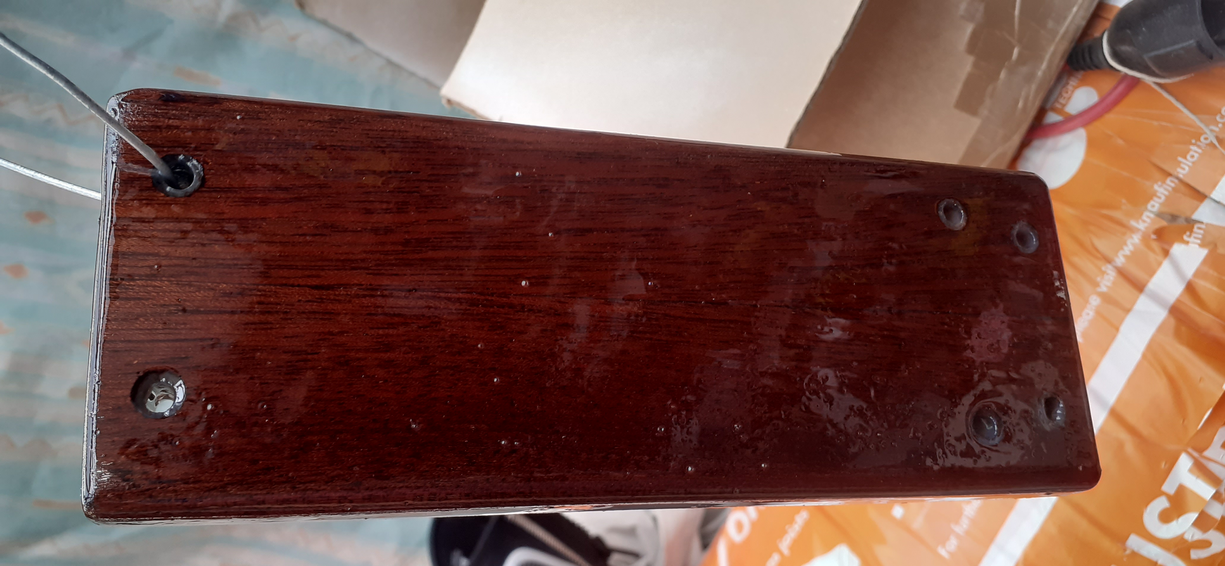
So, it's been super hot today, 30c in the shade, so the shed was pretty hot. I am not sure if this contributed, but, here's the less than satisfactory results. You can see it has bubbled quite badly. Luckily it was dry in 8hrs sufficiently to sand well, so I've sanded it back to flat and re-done it..... which has also bubbled but not as badly. I figured the bubbling was due to the dry heat of the shed causing the air in the wood grain to expand, but this can't be the case with the second coat since there's no open grain exposed. In both instances, I used a heat gun and or blow torch to pop any bubbles as they arrived. There were a lot almost immediately the first time, but I left it too long before re-checking the second time and some had turned up in the interim.


Here's a few pictures of the second coat. I'm actually tempted to leave this. It isn't perfect, but, maybe it'll be okay if I sand it lightly on the visible face and then polish.

After a third coat.... many less bubbles this time. It's a little uneven coated, but I'm loathe to sand and polish it when its so shiny. I actually just noticed I've forgotten to attach the clip that prevents the rudder falling off, so I need to do that.... more drilling, plugging and re-drilling required 🤣

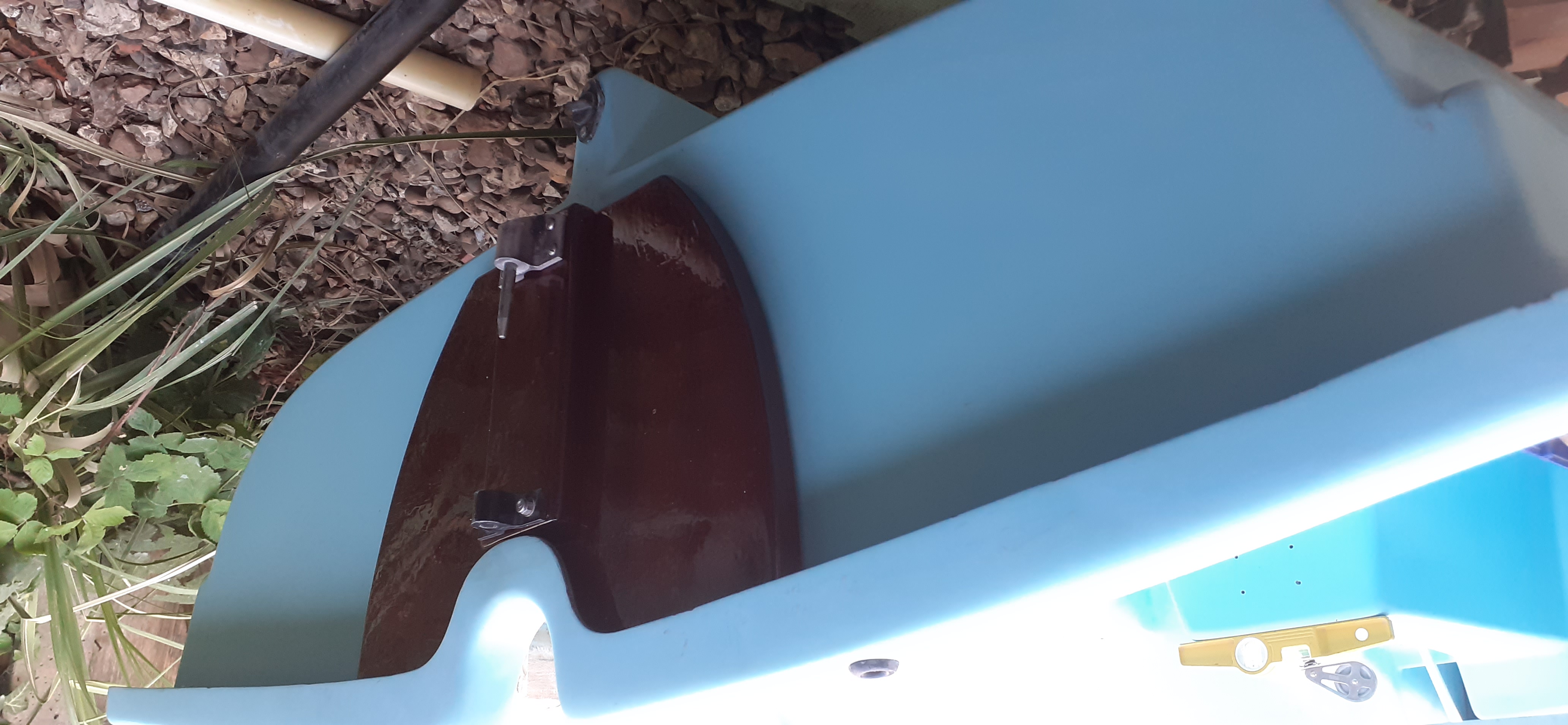
Here is the final product attached to the boat